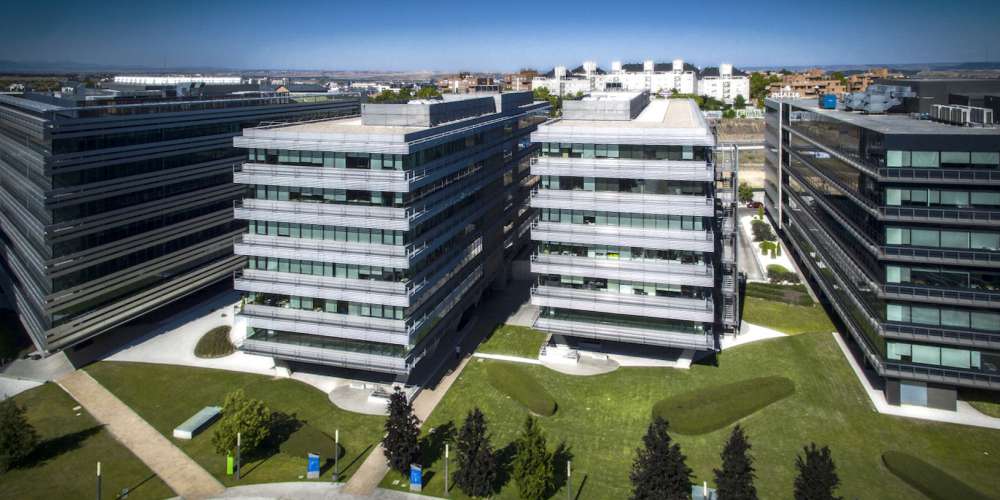
The Social Headquarters for the Municipal Transport Company (EMT) of Madrid consists of two buildings above ground level and three basements levels which are shared by both buildings.
Building 1 is an unconventional construction. From ground level, two concrete towers rise upwards which, on one hand, house the vertical communication shafts and, on the other, serve as supports for two large solid-webbed steel girders with a maximum depth of 4.55m. The distance between the supporting axes is 53.20 m, overhanging 26.35m northwards and 7.5m southwards.
Five slabs (four floor level and roof) are hung from the aforementioned main steel girders. Therefore, a large open space for all floors and the ground floor (level 0), completely free of supports and visual obstacles, is obtained. The struts, from which the floors are subsequently suspended, are slender in design with a minimum possible diameter, including their exterior cladding, in order to make patent their structural usage as hanging elements which are submitted to tension from crowned beams.
The slabs are composed of transversal steel beams perpendicular to the longitudinal axis of the building which are suspended from struts. Purlins are placed between the transversal beams, following the longitudinal axis, thus giving support to the composite floor decking which is based on corrugated steel sheet with concrete cast in situ.
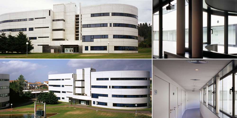
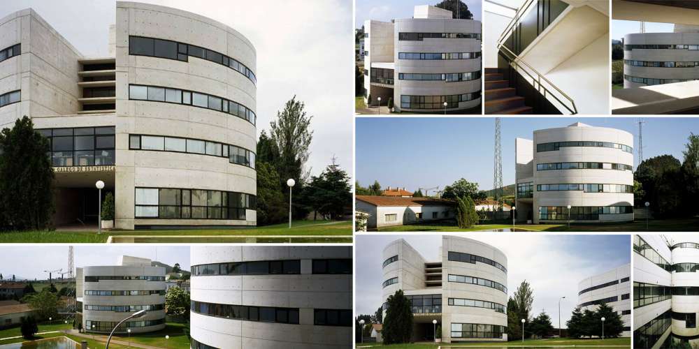
Building 2 is completely made of concrete. It is composed of three concrete slabs. The first and third one (roof) are 1.1m deep light slabs. The intermediate one is a ribbed slab and consists of two 1.10m deep beams and a 0.20m deep slab. The slabs are set on reinforced concrete walls which are placed 14.40m apart and overhang the external walls by 7.20m. As the intermediate slab’s layout does not permit a 7.2m overhang, structural walls have been placed at the edges of the slabs, in such a way, that the intermediate floor slab may rest upon said wall, and thus transmit the slab loads from the roof and first floors.
Running between both buildings is a steel gangway which is supported on building 2 and suspended from the girders in building 1. A steel ladder which runs from ground floor level is another possible access to this gangway.
 We use cookies by Google Analytics for statistical purposes.