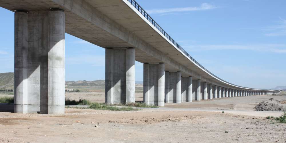
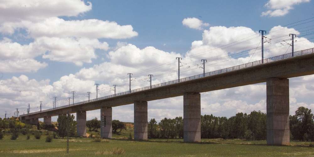
The projected structures (Viaducts 1, 3 and 4) are all composed of a single deck (13 spans in the case of viaduct nº1, 4 spans in the case of viaduct nº3 and 6 spans in the case of viaduct nº 4. The extreme spans are 25.0m in length and the intermediate spans are 32.0m which give total lengths of 402.0m in the case of Viaduct nº1, 114.0m in the case of viaduct nº2 and 178.0m in the case of viaduct nº3. The width of the deck is a constant 14.0m in all cases.
As these viaducts are moderate spans (32.0m) the slab type chosen for the deck is light with a constant depth. This solution offers a greater aesthetic advantage against the box section solution, as it is shallower and offers a more rational structural solution for spans in the range of 30.0m to 35.0m.
All the viaducts have the same transversal cross section which is consistent with a light pre-stressed concrete slab, 1.90m in depth and 14.0m in width. The inferior base width is 5.20m with lateral faces running up at an angle of 62.3º to the horizontal and 3.70m cantilevers.
Regarding the configuration of connections of the superstructure with the substructure the following typology has been chosen:
- In the case of viaduct nº1, as it is impossible to concentrate the total transmission of longitudinal horizontal loads as a result of the sheer size of the structure, longitudinal dampers have been chosen which will work under traction- compression at abutment nº1. The rest of the supports, both in abutment nº2 as in all the piers are free in this direction. Transversally the loads are transmitted longitudinally down through the piers via pot bearings, and in the abutments through stubs set on the base of the deck which also act as stops, so preventing transversal movement.
- In the case of viaducts nº3 and nº4, as a result of their moderate lengths, as well as the moderate seismic acceleration in the calculation (ac= 1.30 x 0.08g = 0.104g), a single fixed point has been placed longitudinally in one of the abutments which will be responsible for capturing all horizontal stop/start loads and the horizontal longitudinal seismic loads. The transmission conception for horizontal loads is similar to that explained beforehand for viaduct nº1, conferring this capacity to the support lines on the piers and to the stubs on the underside of the deck at the abutments.
The viaduct piers have variable heights running between 8.0m and 24.6m. They consist of a central web which is 2.70m wide and 0.80m thick finished off with rounded edging which has a 1.42m radius, therefore giving the pier a total width of 5.20m which coincides with the deck base and the maximum longitudinal depth of the pier is 1.70m. The pier foundations are fulfilled according to the soil conditions at each support and are either direct foundations or via four 1.50m diameter piles.
The abutments are closed in all cases and follow the same aesthetic lines as the piers. Their foundations, as with the piers, have typological variations, depending on the geotechnical characteristics of the overlaying soil.
 We use cookies by Google Analytics for statistical purposes.